
The keys to optimal radiant system performance
November 9, 2018 | By Mike Miller
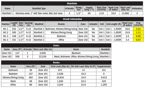
Figure 1 Radiant loop summary
Controls play an integral role in ensuring today’s hydronic radiant systems operate as energy efficiently as possible while still providing ultimate comfort to the consumer. Every system should, at the very least, be employed using outdoor weather compensating controllers or even better yet, controllers that will also be able to increase efficiency and comfort by adding indoor temperature feedback into the control system’s algorithm. This technology has been around for over two decades. If you want a refresher on this topic, check out an article I wrote in HPAC January/February 2012.
In addition to the basics, there are other things to consider to ensure optimal radiant system performance.
First and foremost, of course, would be a proper heat load analysis of the building and zones within. All radiant manufacturers have software available so you can do the analysis yourself, have it provided by a distributor, or most manufacturers offer heat load analysis as a paid service.
The heat load analysis will also provide you with a suggested number of loops required per zone, the individual estimated loop lengths and the desired flow through each of those loops. An example of flow requirements in a very small residential structure can be seen in Figure 1.
Balancing the loops for flow based on loop lengths is a very important practice to eliminate warm and cold spots on the floor surface. Perhaps you have seen radiant installations where warm and cold spots were a reported issue? If the tubing was installed with even spacing throughout, more often than not, the major contributor for this complaint is the lack of balanced flow through the loops.
Best practice would suggest that each loop is balanced automatically if all loop lengths are kept the same. While this may be doable on paper, in practice, it is unlikely to be attainable unless it is a large, square or rectangular commercial structure.
Applications with single manifold for zoning using loop actuators
In order for the loops to be balanced in a non-perfect (on paper) system or field installation where a single manifold is used for zoning using loop actuators, there are two control options:
1. Use manufacturer recommended balancing valves
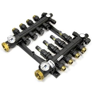
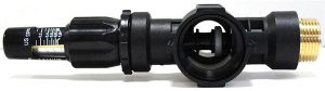
Figure 2 (top)Single loop balancing valve with flow indicator. (Bottom) Engineered polymer manifold with balancing valves with flow indicators as part of the manifold.
Most radiant manifold manufacturers provide a means of loop balancing right at the manifold and for each loop connected. The means of balancing can be right inside of the manifold itself, either found on the supply header with an adjustable stem adjusted by means of an allen key, or through added balancing valves that often come with a flow indicator as seen in Figure 2.
Another option is to add an external balancing valve that is typically installed on the supply header of the manifold on each loop. Manifold loop actuators are then added to the return connections for each loop to allow for the loops to be split into different zones.
2. Self balancing loop actuator
There is a manifold loop actuator available now with a set of supply and return sensors that can be strapped to the supply and return tubing for each loop. See Figure 3 for an example. The loop actuator comes pre-programmed with a 7C differential that will allow the loop to be modulated to maintain that deltaT.
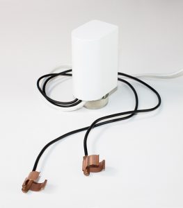
Figure 3 Manifold loop actuator with supply and return sensors for deltaT control
Just like any other actuator, a thermostat calls it into operation when the zone is calling, but rather than to just go fully open or fully closed, upon a call for heat, this actuator will modulate to maintain the deltaT, thus automatically balancing each loop to the right amount of flow needed. This kind of technology pretty much eliminates all of the guesswork whereas in option 1, the flow rate is an ‘estimate’ based on the calculated ‘estimated’ loop lengths.
Granted, being close to the estimate will suffice most of the time.
Applications with single zone manifolds
Both of these options above work well with manifolds used for zoning of multiple rooms connected to the same manifold. But what if a complete manifold is used to supply heat to a single zone? Option 1 will still be required and desired, unless all loop lengths are equal or pretty close to that. It is still an option to increase efficiency of the radiant system by controlling the deltaT across the manifold itself. This can be done by zoning with pumps that have a supply and return sensor and will modulate to maintain a desired deltaT across the manifold, as shown in Figure 4. The mechanical for that pump is shown in Figure 5. You could have multiple manifolds in a system–this setup would be duplicated for each.
If a pump does not have the control logic and capability within, an external deltaT controller can be added that will control the speed of the pump either through a modulating signal of 0-10Vdc, or, by changing the frequency and voltage provided to it, using a triac.
Commercial applications using larger manifolds
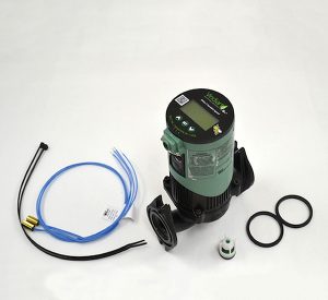
Figure 4 Pump with control logic
In larger commercial applications where multiple manifolds are used for the same zone and where the flow rate required is greater than what can be achieved with a pump with the modulating logic built in as in the last example, modulating for each manifold can be achieved by installing larger two-way modulating valves on the supply to each of the manifolds.
Each would have its own deltaT Controller with supply and return sensors. Then a larger system pump could be used that modulates based on Pressure Differential (deltaP). Some light commercial pumps have this technology already built in and in many cases come with ECM motor technology.
Larger commercial pumps utilize drives that come with external pressure differential sensors, or more modern pumps nowadays operate with a technology where deltaP operation is achieved without the use of external deltaP sensors (see HPAC February 2015 for more details on this technology).
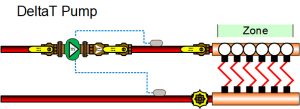
Figure 5 Single zone manifold with deltaT pump
Aside from the wired technology discussed here, wireless has been around for some time and major advances have been realized. It is expected to replace wired radiant slab controls in the not too distant future. Keep an eye out for an article focusing on wireless technology available for radiant systems. <>
Mike Miller is director of sales, commercial building services, Canada with Taco Inc. and a past chair of the Canadian Hydronics Council (CHC). He can be reached at hydronicsmike@tacocomfort.com.

